Transform a Vintage Casio Organizer into a Modern Digital Powerhouse
Introduction
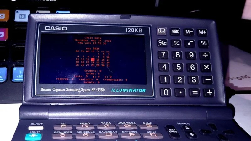
Remember those slim digital organizers from the mid-90s? They looked like miniature laptops but could barely hold a dozen contacts and a few calendar entries. One such device, the Casio Business Organizer Scheduling System SF-5580, has been given a second life thanks to [TundraLegendZ], who replaced its outdated internals with a Raspberry Pi Zero and a Raspberry Pi Pico. The result is a retro-futuristic handheld that runs modern software on a crisp color screen, with a battery that lasts hours. This guide walks you through the same transformation—no advanced engineering degree required.

What You Need
- Casio SF-5580 (or similar model with a full keyboard)
- Raspberry Pi Zero (any variant, but Zero 2 W is recommended for extra speed)
- Raspberry Pi Pico (for keyboard interfacing)
- Small color LCD screen with 480×800 resolution (e.g., SPI or DPI interface)
- 6000 mAh lithium‑ion battery (or similar capacity)
- Battery management module (e.g., TP4056 with protection)
- MicroSD card (16 GB or larger) with Raspberry Pi OS
- Soldering iron, flux, and solder
- Jumper wires, ribbon cable, and heat shrink tubing
- Small screwdrivers, tweezers, and plastic pry tools
- Multimeter (for testing connections)
- Hot glue or 3D‑printed brackets (for securing components)
Step‑by‑Step Guide
Step 1: Disassemble the Casio Organizer
Carefully open the case using a plastic pry tool to avoid scratching the plastic. Remove all screws (typically under the battery cover and inside the compartment). Gently separate the front and back halves. Unscrew the PCB and detach the original LCD ribbon cable. Save the keyboard membrane and the metal frame—you will reuse them. Remove the original battery contacts and any remaining foam or spacers.
Step 2: Prepare the Raspberry Pi Zero
Flash Raspberry Pi OS Lite (or the full version) onto the microSD card. Insert the card into the Pi Zero. Solder a 2×20 pin header to the GPIO pads if not pre‑installed. Connect a USB‑to‑serial adapter to debug the initial boot, or set up ssh and Wi‑Fi in the boot partition. For the LCD, identify the pinout of your chosen display and solder corresponding wires to the Pi’s GPIO—common choices are SPI mode (using SCLK, MOSI, MISO, CS, DC, RST).
Step 3: Integrate the Color LCD
Measure the opening where the original screen sat. If your new display is slightly larger, file down the plastic bezel or 3D print an adapter bracket. Connect the display to the Pi Zero using the appropriate interface (detailed pinout mapping is critical—double‑check datasheets). Secure the screen with double‑sided tape or hot glue. For the 480×800 resolution, you may need to edit config.txt to enable the correct framebuffer settings (e.g., dtoverlay=waveshare35b or a custom overlay).
Step 4: Interface the Original Keyboard with the Pico
The Casio’s 82‑key matrix is a standard row‑column arrangement. Use a multimeter to map which contacts close when each key is pressed. Solder the keyboard membrane’s tail to a ribbon cable, then connect each row and column to separate GPIO pins on the Raspberry Pi Pico. Write a simple CircuitPython script (or MicroPython) that scans the matrix and sends USB HID keypresses to the Pi Zero via serial or direct USB connection. Mount the Pico inside the case using a small protoboard.
Step 5: Add the Battery and Power Circuit
Connect the 6000 mAh battery to a TP4056 charging module. Ensure the module’s output goes through a 5V boost converter (the Pi Zero expects a stable 5V). Wire the boost converter output to the Pi’s 5V pin (pin 2 or 4) and ground. For the Pico, you can power it from the Pi Zero’s 3.3V rail or a separate regulator. Important: include a power switch inline with the battery to prevent draining. Test voltage with a multimeter before final connection.
Step 6: Assemble and Test
Place all components inside the casings, taking care to avoid shorts. Use Kapton tape or epoxy to insulate exposed solder joints. Reattach the keyboard membrane and close the case. Power on and verify the display boots to a desktop or CLI. Press every key on the original keyboard to ensure the Pico firmware maps each one correctly. Adjust GPIO definitions in the firmware as needed.
Step 7: (Optional) Hack the Buzzer for Chiptune Sounds
The original device has a piezoelectric buzzer. Connect it to a spare GPIO on the Pi Zero (via a transistor driver, as the buzzer draws more current than the GPIO can supply). Write a small Python script that uses PWM to generate ringtone‑like melodies. You can even port classic chiptune songs to the buzzer—though the result sounds more like a mobile phone than a retro arcade machine.
Future Upgrades
Once the basic system runs, you can add a HackRF One module for radio hacking, or install a GPS module. The generous 6000 mAh battery leaves room for extra peripherals.
Tips for Success
- Take photos during disassembly—the spring contacts and ribbon locations are easy to forget.
- Test connections incrementally: power the Pi Zero on a bench before final assembly.
- Use a voltage regulator for the Pico if powering from the battery—direct Li‑ion voltage (4.2V nominal) is too high for safe operation.
- Heat sinks on the Pi Zero help if you plan to run CPU‑intensive tasks like web browsing or retro gaming.
- Consider a 3D‑printed backplate to replace the original battery door, providing space for the larger lithium pack.
- Back up your SD card regularly—the microSD slot on Pi Zero is finicky and can corrupt if power dips.